Mr. Juma lives at Mtoni mtongani with his elder parents and a handicapped man along side with his family in his residential house. Hence Mr. and Mrs. Juma all they work at the National Board of Statistical (NBS). so, every day they wake up in the morning for having been early in work. So, according to home environment he supposed to employ other domestic workers to simplify works and helping his parents and a handicapped one.
Many times it becomes too tiring to operate the electrical switches manually every now and then. This is a big problem especially in case his elders and a handicapped man. His parents and a handicapped man have been finding it difficult to turn on and off the lights. Therefore Mr. Juma decided to employ a domestic workers who helps his parents and a handicapped man to turn the lights. Therefore this project aims in reducing this problems through designing an electronic system for switching on/off the lights by using phones.
PROJECT OBJECTIVE
To enable the elders and a handicapped man to control the lights due to proposing an electronic system for switching on/off the lights by using a phone.
SIGNIFICANCE OF PROJECT
Help to reduce the unnecessary consumption of power.
Reduces the disturbance of switching on and off the switches manually.
The system will improve the efficiency.
LITERATURE REVIEWS
This section involves passing through the existing system and other related projects done by other researchers. Also it involves passing through the different sources of information such as internets, books and articles, which contributes positively to my project. Literature review categorized into
Block diagram of existing system
BLOCK DIAGRAM OF AN EXISTING SYSTEM

DISADVANTAGES OF AN EXISTING SYSTEM
High power consumption
Low efficiency
It respond slowly
Neither portable nor easy to use
BLOCK DIAGRAM FOR PROPOSED SYSTEM

ADVANTAGES OF PROPOSED SYSTEM
Low power consumption
Easy to maintain and repair
Efficient and low cost design
Portable and easy to use
Proposed Circuit Diagram
BJT Transistor is a fully electronic device
which remains in ON state as long as the control signal is
available. Transistor has three pins Collector C, Base B,
and Emitter E.
Types of Bipolar Junction Transistor (BJT).
a) NPN Transistor
BC547, BC548, BC549
b) PNP Transistor
so, BC557, BC558, BC559
According to our application we choose a NPN type to use
as a switch.
The BC547 is a NPN transistor meaning when power is
applied to the base ( Control pin) it will allow the current
to flow from collector to the emitter .Typically NPN
transistors are used to Switch a device , meaning they
are placed after the load in circuit.
Specifications
Maximum current , IC≤200mA
Frequency transition 1KHz
Maximum Power ≤500mW
Amplification factor, β= (120-150)
TRANSISTOR CALCULATION
so IB=IC/β
IB = (200×10-3)/135
Hence IB= 1481µA
Since, MCU voltage drops to 4V, VBB= 4V
RB= (VBB−VBE)/IB
(4-0.7)/1481µA
hence 2.2KΩ
Will use RB= 2.2KΩ from Standard Resistors values
RELAY ANALYSIS
According to the power supply available in MCU, so the SPDT Relay with 5VDC electromagnetic coil will be taken into consideration.
Since
IC=Irelay≤200mA, Vcc= 12VDC
Then Relay coil resistance, Rrelay
Rcollector=Rrelay= 12/200m=60Ω
POWER SUPPLY ANALYSIS
How to calculate the values of capacitors for 5VDC
power supply.
so we have Vs=220, f=60Hz.
so Transformer reduces the amplitude of 60Hz sine wave from 220VAC to 12VAC and 12VDC,5VDC power will need to output at most 1A, current.
Since reservoir capacitor placed after bridge
rectifier, will have Vmax=12VAC on it, which is
amplitude of sine wave. Then we start making
some calculation
The discharge time of reservoir capacitor in case of
half wave rectifier is T discharge=1/f=1/60
T=16.6ms.
Principal operation of a proposed circuit diagram
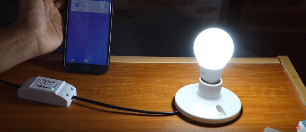
This project helps to control the home lighting with the help of android application. The home lights are controlled based on Bluetooth input signal. This input signal is received from the android device with OS. The app also provides an effective GUI for providing this functionality.
An ATmega328 microcontroller is used in this system. The Bluetooth receiver is interfaced with microcontroller in order to accept the commands and then react accordingly. It operates the loads (lights) through a set of relays using a relay driver IC. Relays are used between loads and the control unit.
CONCLUSSION
After designing and testing the model of this an electronic system for controlling the lights for Mr. Juma’s residential house by using phone, the system provide better result output as a reliable modern and reduce the disturbance of switching ON/OFF the lights manually for a handicapped man and his elder parents. This system has been designed to meet basic requirements of a special groups especially elders and handicapped man in term of level of technology we have so far, as that it is simple and easy to employ and operate.
RECOMMENDATION
Since we will be using 220V devices with these relays, we have to take special precautions. So I recommend that Never touch or even go near the relay when it is plugged into the wall power socket via a cable. If possible, hide the relay where other people cannot access it, for example, in a plastic enclosure.