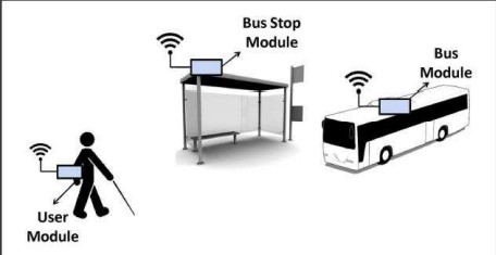
Bus information is an essential part of many intelligent transportation systems (ITS) applications in today’s world where everything is connected. India’s automobile population has significantly expanded in recent years, which has resulted in severe traffic congestion and pollution in metropolitan areas, especially during rush hours. Increasing the number of individuals who use public transportation instead of their own automobiles is an ideal solution to these problems (comfort, convenience and so on). The suggested system would employ a speech recognition system to enter the user’s chosen location and a voice module to notify the arrival details. The suggested system’s performance has been found to be encouraging, and it is anticipated to be helpful in India’s development of advanced public transportation systems (APTS). The major benefit of this gadget is that it offers a bus alerting system for simple navigation; the user receives notifications for their destination as well as voices that announce the bus’s data. The system also has a further blind protection function that, in the event of any abrupt accidents, detects them using a MEMS accelerometer sensor and sends SMS-based location-based notifications to the designated person of concern.
Everyday struggles are different for each visually impaired person.
A number of behaviors, including learning and notably movement, are compromised because of their inability to perceive what is going on around them. The difficulty increases if they have to take public transit. Additionally, they rely on the goodwill of those around them in order to find the public transportation vehicle. They frequently aren’t even aware that they are at a bus stop. It is necessary to conduct research and develop systems that could enable these individuals to independently locate and utilize the public transportation system, just like a regular person, in order to increase their comfort and quality of life while using public transportation.
PROBLEM STATEMENT
PROJECT OBJECTIVES
The main objective is to design alerting system that will provide an effective communication.
SIGNIFICANT OF THE PROJECT
LITERATURE REVIEW
In literature review describes the details and important things in alerting system focusing on the present system which are being used and the proposed system.
DISADVANTAGE OF EXISTING SYSTEM
It is difficult to the passenger when the travelling to identify bus station because there is no user interface which can help a passenger to identify easily.
PROPOSED SYSTEM
BLOCK DIAGRAM

PRINCIPLE OF OPERATION OF THE PROPOSED SYSTEM


ARDUINO ATMEGA
DISPLAY ANALYSIS
Proposed circuit

CONCLUSION
According to the function performing by this project the objective of providing effective communication between passengers and operators of the bus will eliminate. This project is beneficial to the transportation facilities that can help passengers to determine the place where they are. The bus’s transceiver is then informed of this location. There is an alarm in the bus unit alerting the presence of blind and a voice is sent to the user’s headset informing them that the specific bus has arrived if the names in the transceiver in the bus match with that of the name sent by the blind. With GPS assistance
RECOMMENDATION
According to the requirement of the proposed solution, the device especially GPS module should be accurate in order to provide accurate coordinates for the accurate location for it to give information to microcontroller by sending appropriate commands to display the current location for which the passenger or operator decided to stop to that location ,then he or she will push the button to buzzer to inform the bus operator to stop the bus.

